Screw feeder for carrying marbles |
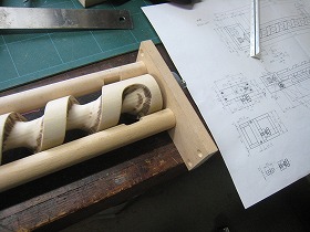
Mar. 3/2019 My grandson is addicted to the I made CUBORO. So I made a screw feeder to return the marbles.Drawing |
 |
 |
|
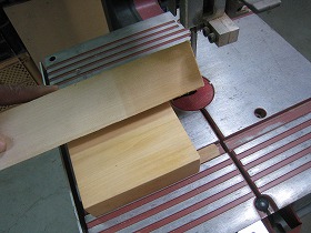
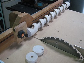
1.The material is acacia. Using the band saw center marker jig, cut the cross groove that insert the drive center. |
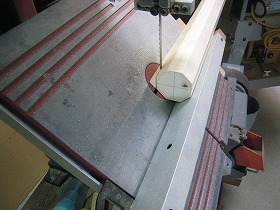
2.Tilt the table to 45 and cut the parts into octagons. |
|
 |
 |
|
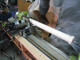
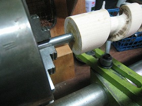
3.Mount the hand made router race on the wood lathe WT - 300. Then turn the workpiece into a 44 mm round bar. |
4.Made a precision round bars. The bit used a 25 mm dish bit. |
|
 |
 |
|
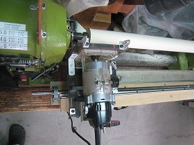
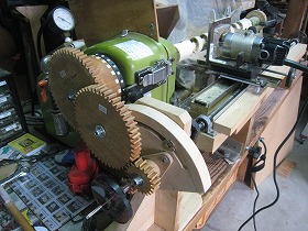
5.Install hand made synchronous gear unit. This device synchronizes the spindle and the rotation of the router race. The bit is a 25 mm dish bit. |
6.In order to set the groove width to 32 mm, if the synchronization gauge of the main shaft is removed and the router race is advanced by 7 mm and then the synchronizing gear is bite again, the groove width spreads to 32 mm. |
|
 |
 |
|
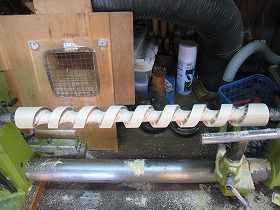
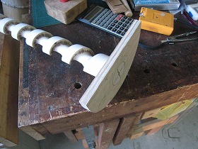
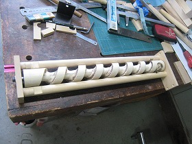
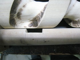
7.Turning the right side boss portion that was left uncut. A screw with a length of 420 mm is completed. |
8.Because the rotation speed of the trimmer was high, it was burned a little. |
|
 |
 |
|
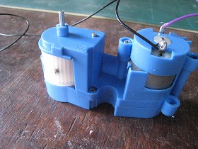
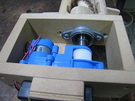
9.Used a toy gaunt unit that was destined to be destroyed in the drive section. Reduction ratio is about 1/118. The diameter of the shaft on the upper side is 2.5 mm in diameter. |
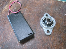
10.This is flange unit UFL000C and, battery holder with switch 2 AA batteries inserted. I bought this in Akihabara. |
|
 |
 |
|
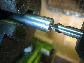
11.This is the drive side shaft to be inserted into the screw. Mark the center with a center drill on a 10 mm SS400 round bar. |
12.Drilling 2.5mm. |
|
 |
 |
|
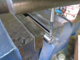
13.Drill a 2.5 mm on the side of the shaft and tap M3. It is for fixing the shaft of the gear unit. |
14.This is a shaft with a diameter of 10 mm to be inserted into the follower part bearing of the screw. Correcting the length. |
|
 |
 |
|
15.Drilling 5mm. |
16.Tapping M6. |
|
 |
 |
|
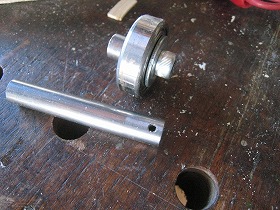
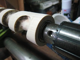
17.The upper side is the set of bearings and fixed shaft of the screw follower part. The bearing is # 6200 ZZ. The lower side is the drive side shaft. |
18.I would like to do hole processing on both ends of the screw with a lathe, but unfortunately it is difficult to I have not a steady-rest. So, Drilled a 43.5 mm hole in a 9 mm plywood, and a screw was inserted there and adhered. |
|
 |
 |
|
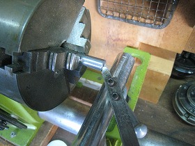
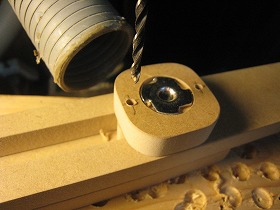
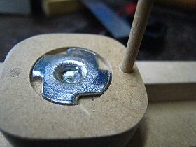
19.Mark the center of the inserted screw and fix it to the vise. |
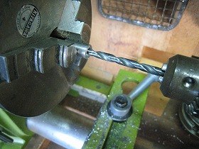
20.First, Drilling 10 mm. Then remove the plywood and lightly paste the opposite side of the screw in the same way. Then drilling the 30 mm hole into which the bearing will enter with a forstner bit. |
|
 |
 |
|
21.Cutting both side unnecessary parts of the screw. |
22.Bonded shaft and screw with epoxy adhesive. Attach to the lathe and check that there is no runout. |
|
 |
 |
|
23.Bond the other side bearing as well. Grabbed the shaft part with the chuck and made the centering. |
24.The stay attached to both sides of the screw is a round bar of 20 mm. Cut out the part where marbles come in or go out. |
|
 |
 |
|
25.Make a temporary assembly and check whether the screw turns smoothly. |
26.When adjusting the flange unit the screw revolution lightly. |
|
 |
 |
|
27.When dropping the marble, it turned out that the notch was too short on the exit side. I found the exact dimensions at the moment and corrected the drawing. |
28.Temporarily fix the gear unit of the drive unit with a vise and mark the position to fix. |
|
 |
 |
|
29.Fix the gar unit with wood screws. |
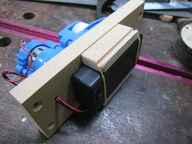
30.Attach the battery holder and wire it to the motor. |
|
 |
 |
|
31.Battery holder is fixed with rubber bands. Because it is why the lid for replacing the battery is behind and the switch is in the table so it was impossible to fix with the screw. |
32.Insert the output shaft of the Gear Unit into the 10 mm shaft of the screw. Then fix it with M3 hollow set screw. |
|
 |
 |
|
33.Make a chute that will be attached to the part where marbles enter and leave. |
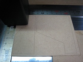
34.Marking the outline of parts with a laser so that it can be easily cut with a fret saw. |
|
 |
 |
|
35.The part on the stay of 20 mm in diameter, It was drilled with 20 mm forstner bit before cutting out with a fret saw. |
36.This is a chute where the finished marbles enter. Make the chute of exit side in the same way. |
|
 |
 |
|
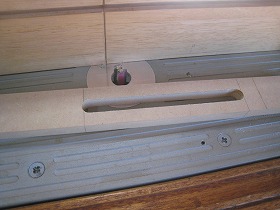
37.Cut the long hole part of the stand with a router. The bit is straight with 12 mm. |
38.Insert the locking pin to prevent the slider fixing screw from idling. For that Drilling 3 mm. |
|
 |
 |
|
39.Used a 3 mm bamboo skewer for the detent pin. |
40.Cut the part interfering with the exit side chute of the stay with the fret saw. |
|
 |
 |
|
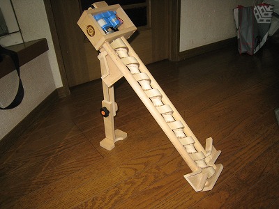
41.Attached the stay and completed the assembly of the whole device. |
42.Behind the chute where marbles enter. |
|
 |
 |
|
43.The back side of the chute where marbles go out. Since the distance to jump out depends on the screw rotation direction, the width of the shoot is changed in the top and bottm. |
44.Shrinking the stay and folding it. |
|
 |
 |
|
45.Behind the inlet chute of marble. This is symmetrical. |
46.Marked the brand mark on the bracket of the gear motor with a laser. |
|
 |
||
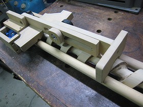
The whole device as seen from above. |
||
 |
||
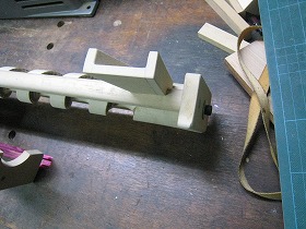
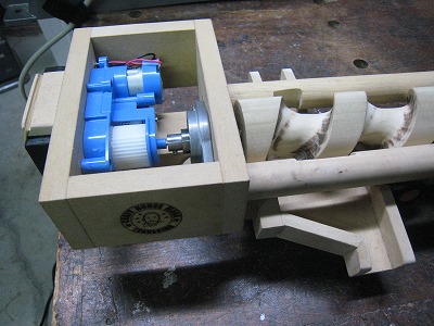
Drive part and marble outlet chute part. |
||
 |
||
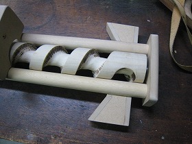
Marble entrance part. |
||
 |
||
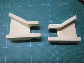
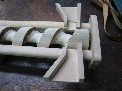
A stay set at 45 degrees. |
||