Stabilizer for wood lathe |
May. 19/2019 I was planning to make a stabilizer for wood lathe for many years. I was keenly aware of the necessity when I made the wood screw feeder at the beginning of this year.Drawing |
 |
 |
|
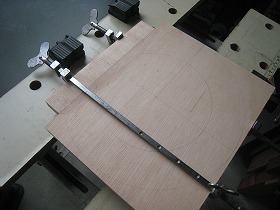
1.Plywood with a thickness of 18 mm was used for the plate to which the bearing guide attached.The part which is a little insufficient in wide was joined with biscuit. |
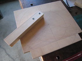
2.First, Marking the donut cutout position and the cut of groove section. And fix the guide of the trimmer with wood screw. |
|
 |
 |
|
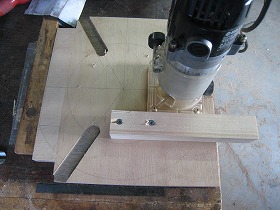
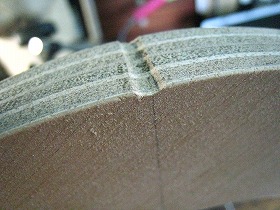
3.Cut the groove with a width of 20 mm depth of 6.1 mm with a trimmer. |
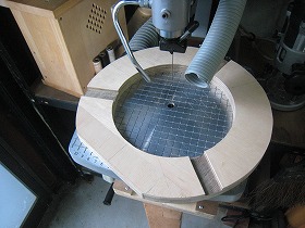
4.Cut it in a donut shape with a fret saw. |
|
 |
 |
|
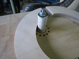
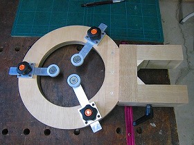
5.Grind the outer circumference with homemade disc sander. |
6.Grind the inner circumference with homemade spindle sander. |
|
 |
 |
|
7.In the center part of the fold in which the hinge is attached, a round groove is put in to eliminate interference with the hinge. |
8.I tried installing a hinge, but I thought that folding had worry of strength and vibration.Therefore I decided to make it in one piece this time. (The drawing has not been modified) |
|
 |
 |
|
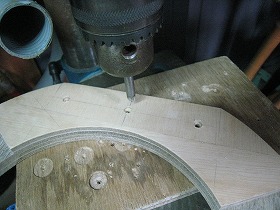
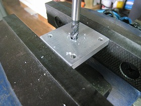
9.Drilling to attach the donut plate to the fixing bracket. |
10.This is leg holding a single pipe of a lathe. It's a 40 mm square piece of japanese ash. |
|
 |
 |
|
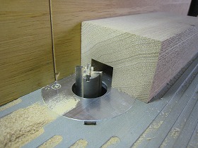
11.Groove processing to insert the bracket to fix the donut plate. Width 18 mm, depth 15 mm. The bit diameter is 15 mm. |
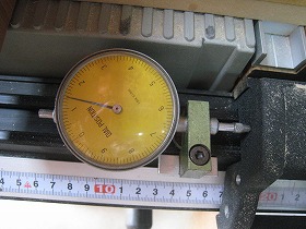
12.Cut it adjusting with fence microtremor system. |
|
 |
 |
|
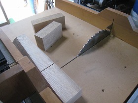
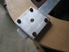
13.Cutting of the 15-degree inclined portion on both sides of the bracket was made with the cutting jig of the segmental bowl member. |
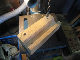
14.The upper part of the stand sandwiching the single pipe of the lathe. Drilling 3.8 mm. |
|
 |
 |
|
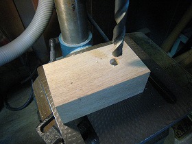
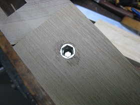
15.Drlling 9mm for insert nut. |
16.Screw the M6 insert nut with a 6 mm Allen wrench. |
|
 |
 |
|
17.Screwing was completed. |
18.Assemble legs in a gate shape. Use screws and adhesive together. Also, bond the triangle to the corner for reinforced. |
|
 |
 |
|
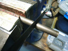
19.Make the insert rod for pipe protection from the 8mm brass rod. It's into the bolt tip of the clamp lever. First cut to a predetermined length. |
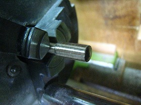
20.Turn the end of the rod to 6mm in diameter. |
|
 |
 |
|
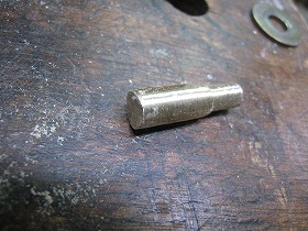
21.Make the tip on the 8mm side the same as R of single pipe by file. |
22.The completed insert rod. |
|
 |
 |
|
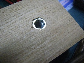
23.Insert the rod into the insert nut for the clamp lever. In the center of the nut is a part with a diameter of 6mm. |
24.The tip of the insert rod to fix the single pipe. |
|
 |
 |
|
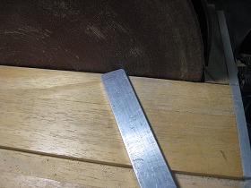
25.The slide bar for mounting the resin bearings is 20 6 t aluminum. Grind the bearing mounting side to R10. |
26.Chamfering on the opposite side. |
|
 |
 |
|
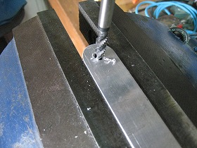
27.Drilling 5mm for M6 tap. |
28.Tap M6. |
|
 |
 |
|
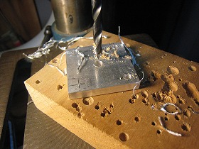
29.Threaded hole in the plate that holds the slide bar. Drilling 3.8mm. |
30.Drilling 5mm for M6 tap. |
|
 |
 |
|
31.Tap M6. |
32.Assemble the slide part and check whether it moves smoothly. |
|
 |
 |
|
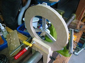
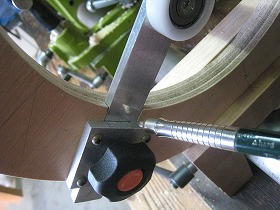
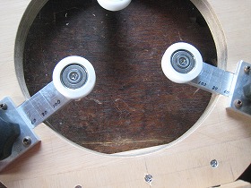
33.Assemble the whole bearing part and check the center. |
34.Temporarily install the stabilizer on the lathe. Find the position where the center of the bearing section and the lathe center meet. And marking its position. |
|
 |
 |
|
35.Preparation for bonding of single pipe fixing base and donut part. |
36.Bonding complete. |
|
 |
||
37.I tried trial running of the stabilizer, I think that it seems that you can work comfortably without vibration. |
||
 |
 |
|
38.Scale o aluminum bar. Fist, Hold the round bar of a diameter of 20 mm with the stabilizer while holding it with the tail stock. |
39.Marking the position while holding firmly. |
|
 |
 |
|
40.Based on the position of 20 mm, mark the position in 20 mm steps and write in the dimensions with the magic pen. |
41.This scale will be a guide for centering. |
|