Pocket hole jig-1 |
 |
 |
|
1.I don't know what the material, it's a purple board. |
2.Use laminated rubber-tree for the stays that support the extension bar and drill guide. |
|
 |
 |
|
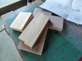
3.Cut parts. |
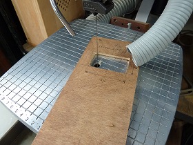
4.Make a template for digging a square hole dust chamber.The material is 5.5mm thick plywood. |
|
 |
 |
|
5.Cut out with a scroll saw. |
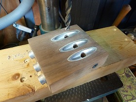
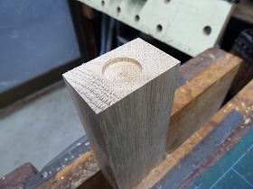
6.In the center of the digging part of the dust chamber, make a spot facing 6 mm deep with a 12 mm fofstner bit. |
|
 |
 |
|
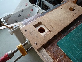
7.Set the template. |
8.Set the 5/8 ”template guide bush on the router. |
|
 |
 |
|
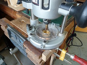
9.Use a bit with a diameter of 12 mm. |
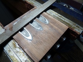
10.Turn the router clockwise, you can dig a square groove. |
|
 |
 |
|
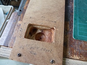
11.When I thought that the chamber groove was completed, I noticed the wrong size of the template. I had no choice but to expand the template hole and correct it to the dimensions as shown in the drawing. |
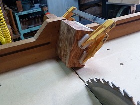
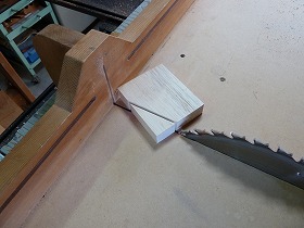
12.Tilt the work along the marking line for the diagonally cut part of the chamber.Then clamp it to the crosscut thread. |
|
 |
 |
|
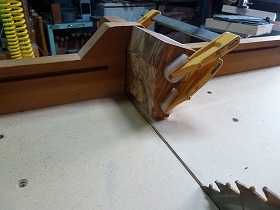
13.It was able to cut diagonally to safely. |
14.Drilling 22mm for dust port. |
|
 |
 |
|
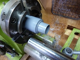
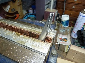
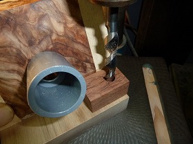
15.Turning the tip of the TS socket 20 * 13 to a diameter of 22 mm. |
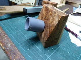
16.Glue to the 22mm hole in the chamber. |
|
 |
 |
|
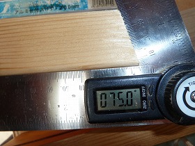
17.From here, make a 15 degrees drilling jig. Make a 75 degrees marking on the 2x4 material and adjust with a piece of wood spacer so that the lines are vertical. |
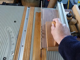
18.Press the board against the fence of the cross-cut sled and cut it. |
|
 |
 |
|
19.It's perfect for 75 degrees. |
20.Glue each part to a 12mm thick MDF board. The drilling jig is completed. |
|
 |
 |
|
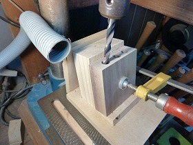
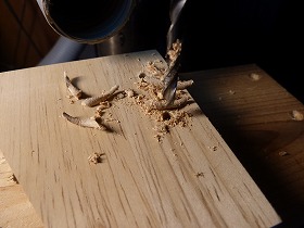
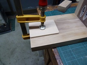
21.Place the plate parts of the drill guide on the drilling jig and drilling 12mm. |
22.Drilling 9mm for dust port. |
|
 |
 |
|
23.Cut an aluminum pipe with an outer diameter of 12 mm and an inner diameter of 9 mm used for the drill guide to a length of 95 mm. |
24.Expanded inner diameter to 9.5 mm. |
|
 |
 |
|
25.Insert the aluminum pipe into the hole of the drill guide plate part and mark the part to be cut diagonally. Then cut along it with a hack saw. |
26.After adhering the aluminum pipe to the guide plate parts, file finish. |
|
 |
 |
|
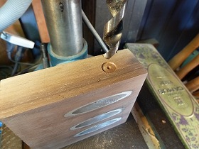
27.Counterbore of insert nut for height adjustment thumbscrew.12 mm dia, 1 mm depth. |
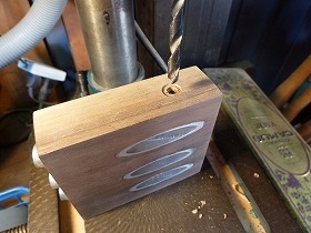
28.Drilling 6mm. |
|
 |
 |
|
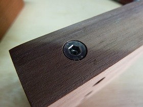
29.Screw in the M4 × 8L insert nut. |
30.Drilling 7.5 mm dust ports in aluminum pipes. |
|
 |
 |
|
31.This is the side support of the chamber and is 20mm thick. Cut diagonally according to the dust collection port. |
32.Drilling 4 mm at both ends of the slotted hole. |
|
 |
 |
|
33.Cut the long hole part with scroll saw. |
34.Screw hole for fixing to the dust collection chamber, 4 mm. |
|
 |
 |
|
35.Do a counterbore. |
36.Drilling for fixing the chamber and side support from the back side of the 26 mm thick base plate. |
|
 |
 |
|
37.Fixed with 3.8 dia* 51L coarse thread. |
38.Drilling a 16 mm dia * 3 mm deep to insert a neodymium magnet. |
|
 |
 |
|
39.Similarly, Drilling to the extension bar for inserting neodymium magnets. |
40.Glue the neodymium magnet with a two-component epoxy, paying attention to the S and N orientations of the magnet. |
|
 |
 |
|
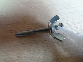
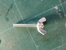
41.Screw the wingnut into the M4 round head screw and apply superglue. |
42.Tighten quickly to complete the thumbscrew. |
|
 |
 |
|
43.The cushioning material attached to the tip of the adjuster bolt of the toggle clamp is a 1t neoprene sheet. Cut to a diameter of 38 mm with circular cutter. |
44.Glued with bond G17. |
|
 |
 |
|
45.Glue 5.5mm plywood to the base plate for toggle clamp mounting seat. |
46.Pilot hole for M5 insert nut, 8mm. |
|
 |
 |
|
47.Screw in the M5 x 13L insert nut. |
48.Screw the insert nuts in 4 places to complete the toggle clamp mounting seat. |
|
 |
 |
|
49.Drilling 10 mm for storing a dedicated drill. |
50.Drilling 3 mm for storing L-shaped wrench. |
|
 |
 |
|
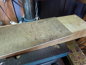
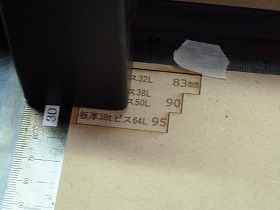
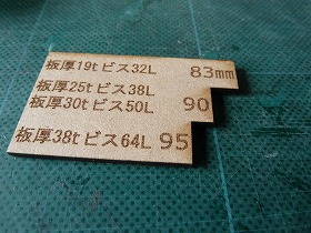
51.A drill stopper gauge for adjusting the drilling depth according to the thickness of the work.The work thickness and hole depth were engraved with a laser machine, and the periphery was cut. |
52.The completed gauge plate. Used a 2.5mm thick MDF plate. |
|
 |
 |
|
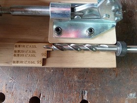
53.Glue the gauge plate to the base plate by aligning the tip of the drill with the stopper at the depth of 83 mm of the drill and the gauge of 83 mm. |
54.Neodymium magnet part that has been bonded. |
|
 |
 |
|
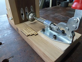
55.The drill guide can be adjusted to any height with the thumbscrew. |
56.Secure the toggle clamp with M5 cap screws. |
|
 |
 |
|
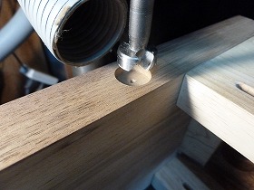
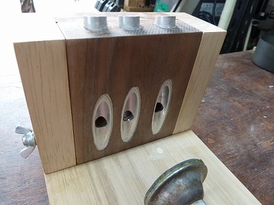
57.Chips are discharged into the chamber through the 7.5 mm hole in the aluminum pipe. |
58.With the drill guide removed. The square groove is the chamber, and the chips enter here and then collect in the central dust port and are discharged. |
|
 |
 |
|
59.Insert a vacuum cleaner hose into the PVC dust port. |
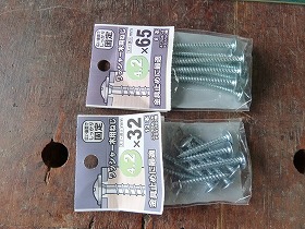
60.Since the screw for the pocket hole joint is expensive, I bought a flat head wood screw with a washer at hardware store, but the washer has a diameter of 10 mm and can not fit in the pocket hole. |
|
 |
 |
|
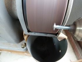
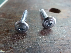
61.Therefore, the washer part was ground by 9.4 mm with a belt sander. |
62.The screw will now enter the pocket hole. |
|
 |
||
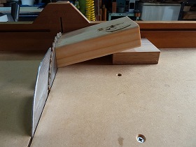
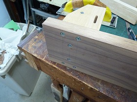
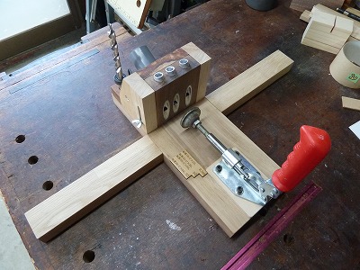
With the extension bar set. Even wide workpieces can be fixed stably. |
||
 |
||
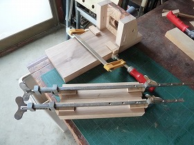
It becomes compact when the extension bar is removed. |
||
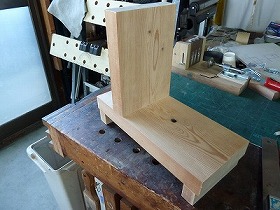
It's the process of making a right-angled guide for jointing.Drawing-3 |
||
 |
 |
|
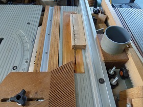
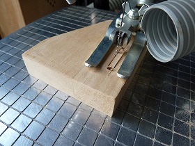
65.The material is a 34 mm thick cedar board. |
66.Completed by gluing the cut parts according to the drawing. |
|
 |
 |
|
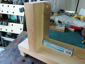
67.It is important that this is a right angle. |
68.Finally, I noticed that I forgot to put a scale on the drill guide of the pocket hole jig. This serves as a mark when moving the guide up and down depending on the thickness of the work. I wanted to engrave with a laser, but I writen with a felt-tip pen becouse It was annoying. |
|
Make the drill stopper gauge with a laser machine. |
||