Round bar making jig |
Jun. 20/2021 I needed a 9.5mm plug for the pocket hole jig, so I decided to make a round bar making jig. I designed 8 types of round bars of 5 to 12 mm so that they can be made from square timber.Drawing |
 |
 |
|
1.Used poplar timber for the part that serves as a guide for the trimmer. Cut to a thickness of 27 mm. |
2.Cut to a width of 46.5 mm. |
|
 |
 |
|
3.Use bubinga, which is hard and has high wear resistance, for the main body. Cut to a width of 66 mm. |
4.Polish the surface with a drum sander. |
|
 |
 |
|
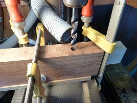
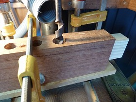
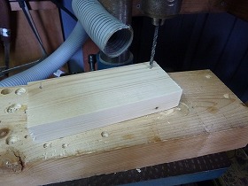
5.Make a notch with a 19 mm bit. |
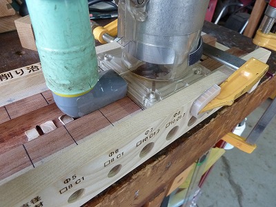
6.Mark the drilling position. The Woodpeckers ruler is useful. |
|
 |
 |
|
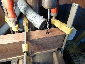
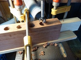
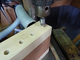
7.Counterbore of 10 mm * 30 mm depth. |
8.Drilling 5 mm through hole. |
|
 |
 |
|
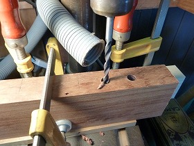
9.Counterbore of 10 mm * 30 mm depth. And Drilling 6 mm through hole. |
10.Counterbore of 12 mm * 30mm depth by forstner bit. |
|
 |
 |
|
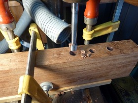
11.Drilling 7mm through hole. |
12.Counterbore of 12 mm * 30 mm depth. And Drilling 8 mm through hole. |
|
 |
 |
|
13.Counterbore of 15 mm * 30 mm depth. And Drilling 9.5 mm through hole. |
14.Counterbore of 15 mm * 30 mm depth. And Drilling 10 mm through hole. |
|
 |
 |
|
15.Counterbore of 18 mm * 30 mm depth. And Drilling 11 mm through hole. |
16.Counterbore of 12 mm * 30 mm depth. |
|
 |
 |
|
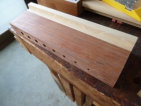
17.Drilling 12 mm through hole. |
18.The main body that has been drilled. |
|
 |
 |
|
19.Drilling holes in poplar wood guide parts. |
20.The hole is one size larger than the hole in the main body. |
|
 |
 |
|
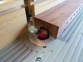
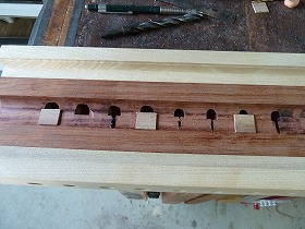
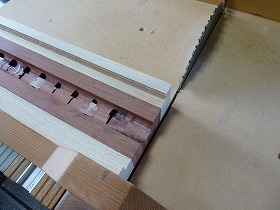
21.Cut the groove with a 25 mm dish bit. |
22.Since the hole position of 5 to 12 mm is slightly offset to the upper limit, there is a place where the grooves are deeply scraped off. It is necessary to fix it. |
|
 |
 |
|
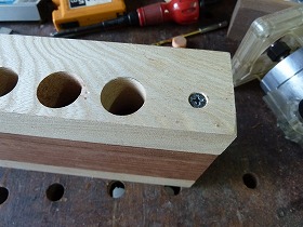
23.Drilling 3.8mm for guided member fixation. |
24.Counterbore for countersunk screw. |
|
 |
 |
|
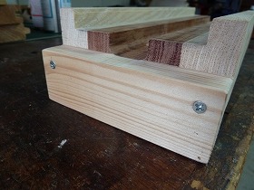
25.Fix the guide member with Coarse Thread. |
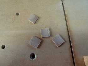
26.This is to correct the groove portions are too shaving, 1mm thick wood. |
|
 |
 |
|
27.Paste it into a part that corrects it. |
28.Modify the depths individually with trimmer.I actually use it and think it is necessary to fix it. I thought that it was better to make a shallow groove from the beginning. |
|
 |
 |
|
29.Cut the end face. |
30.This is a jig's leg Two-by-Four, and 3.3 mm perforated for fixation. |
|
 |
 |
|
31.Securing the leg to the body |
32.Marking the position to fix the trimmer with Magic Pen. |
|
 |
 |
|
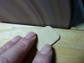
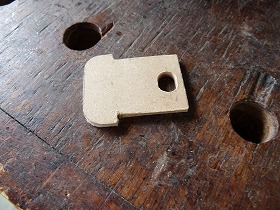
33.A 2.5 mm thick MDF so that the chips do not splatter, Makeing a plate that closes one side of the trimmer. After cutting out, Sanding the corner to round with a disk sander.
|
34.Drilling 6mm. |
|
 |
 |
|
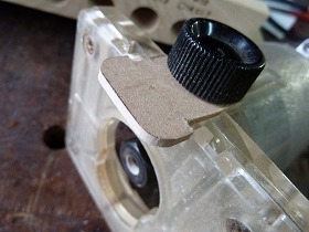
35.Make it a long hole so that the position can be adjusted. |
36.Use the knob bolt of trimmer guide for fixation. |
|
 |
 |
|
37.Since there is a gap, air for dust collection can be sucked in. |
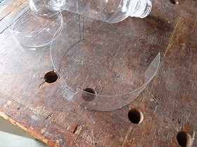
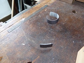
38.This is also a parts that improves dust collection efficiency. It is a cover that closes the window that is open at the base of the trimmer by processing a PET bottle. Height 45 mm * length 200 mm. |
|
 |
 |
|
39.Attach velcro to both sides. |
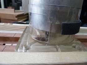
40.Wrap it around the trimmer base in this way and fix it with Velcro. |
|
 |
 |
|
41.Hard to see in the photo, but the trimmer base window is blocked |
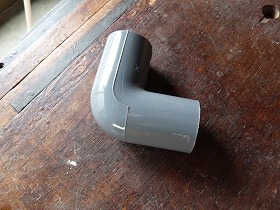
42.Make a dust collection port with a 20A PVC elbow. |
|
 |
 |
|
43.I forgot to take a picture of the process of making. Burn it with a burner, crush one side of the elbow a little, and then use a belt sander to cut it to a thickness of 27 mm so that it fits in the groove. The tip is stepped so that it can be inserted between the trimmer base and the jig. |
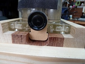
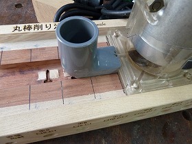
44.The elbow is inserted between the base and the jig. |
|
 |
 |
|
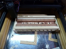
45.Engraving the name of the jig with a laser. |
46.It can be stamped like this with an output of 3.5W, 100%, and 2500mm/min. |
|
 |
 |
|
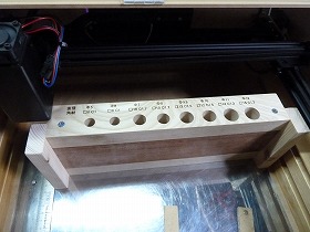
47.Similarly, engrave the diameter of the round bar and the dimensions of the blank square lumber. |
48.The C dimension represents the chamfer dimension. This is a painstaking measure. If the square timber was designed with larger dimensions, such chamfering would not have been necessary. It is the second of remorse. |
|
 |
 |
|
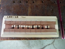
49.The front of the completed jig. |
50.Seen from above, the board pasted by adjusting the depth is sad. |
|
 |
 |
|
51.From here, we will make a socket to turn the square timber. First of all, cut out 20 * 16 * 60 L square lumber with japanese ash.Drawing |
52.Polish the surface with a disc sander so that it fits into the aluminum channel. |
|
 |
 |
|
53.Cut the aluminum channel to a length of 35 mm.There is a hole because I used a junk item. |
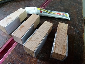
54.Glue japanese ash and aluminum with Cemedine Super X. |
|
 |
 |
|
55.Grasp the aluminum side with a four-claw chuck and turning the other side to 9 mm. |
56.Next, grab the round bar with a three-claw chuck and make a pilot hole for a square hole. |
|
 |
 |
|
57.Corrected to a square hole with a chisel. |
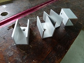
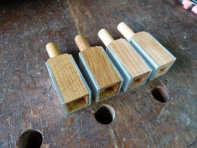
58.Completed 4 types of sockets. |
|
 |
 |
|
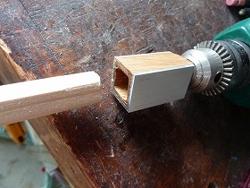
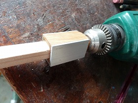
59.To use the socket, first chuck the socket with a drill. |
60.Then insert the square timber. The square holes should be slightly tight. |
|
 |
||
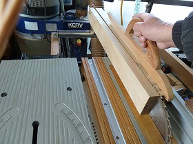
Then how to use.First, fix it to the work table with an F-type clamp. |
||
 |
||
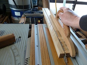
The trimmer can also be firmly fixed with an F-type clamp. |
||
 |
||
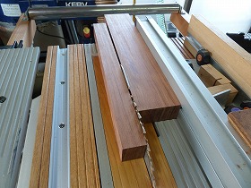
Dust collection is perfect. |
||