Tip saw sharpener for brush cutters |
Aug.11/2024 The tipped saws used for brush cutters cut hard grass stalks, bamboo, and wood, and also come into contact with soil, so they wear out quickly and lose their sharpness. So I decided to make my own sharpener.Drawing |
 |
 |
|
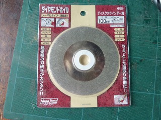
1.I decided to use a diamond wheel made by Three Hand for a 100mm diameter disc sander that I bought at a hardware store. The inner diameter of the wheel is 20mm, but a bushing with an inner diameter of 15mm is included. |
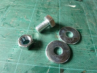
2.First, make the parts to attach the diamond wheel to the baby motor. The materials are M12 bolts and nuts and M10 large washers. The mechanism is shown in Drawing-1. |
|
 |
 |
|
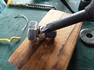
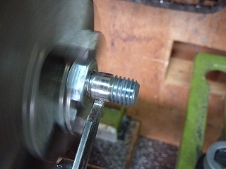
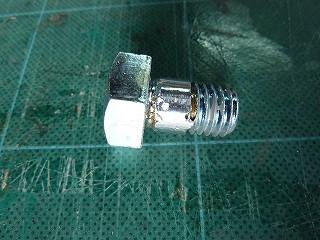
3.I wanted the part where the diamond wheel would go to be flat, so I decided to fill in some of the screws with solder. |
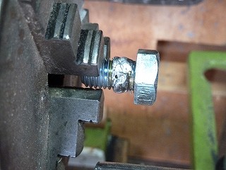
4.In order to turn the soldered part with a lathe, I replaced the chuck on the wood lathe with a three-jaw chuck. |
|
 |
 |
|
5.It's better to grab the head of the bolt, so I chucked it again and used a parting tool to turn it into a flat piece with a diameter of 12mm. |
6.The edges of the solder are a little dirty, but I don't think it's a problem. |
|
 |
 |
|
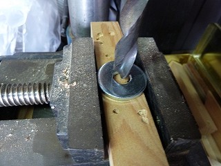
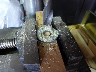
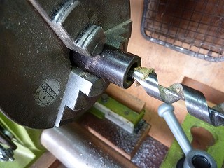
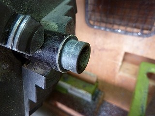
7.A M10 flat washer with a large and thick outside diameter that I found at a home improvement store. To make the inner diameter 10mm, place an auxiliary plate in the vise of the drilling machine and fix it. |
8.Expand the hole with a 12mm drill. |
|
 |
 |
|
9.An adapter ring is required to attach the 15mm inner diameter bushing of a diamond wheel to a 12mm bolt. When I searched through the box to see if I could find the right material, I found a round Bakelite rod, so I decided to process it. First, drilling a 12mm. |
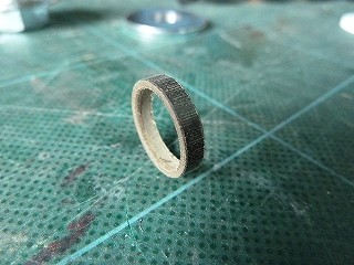
10.Finish the outer shape to 15mm and cut it to a width of 3mm using a parting tool. |
|
 |
 |
|
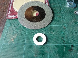
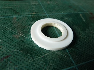
11.The completed spacer ring. |
12.Diamond wheels and included bushings. |
|
 |
 |
|
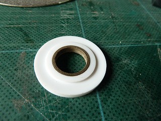
13.The bushing is stepped, and the diamond wheel is placed on the outside of the step. |
14.Insert the spacer ring into the bush. It's a perfect fit with just the right fit. |
|
 |
 |
|
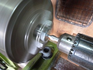
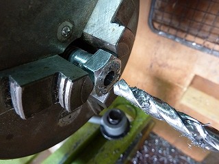
15.Next is drilling the M12 bolt shaft. First mark the center with a center drill. |
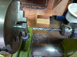
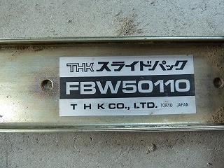
16.Drilling 6mm. |
|
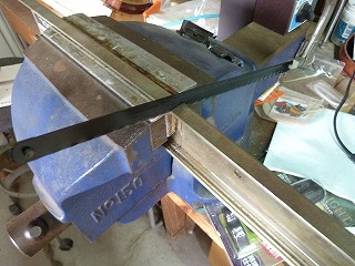
 |
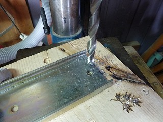
 |
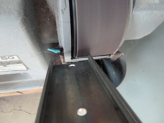
|
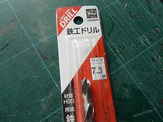
17.The baby motor shaft was an odd size at 7.3mm, so I ordered a new drill online. |
18.Drilling a 7.3mm. The new drill bit cuts well. |
|
 |
 |
|
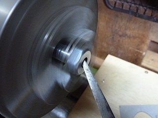
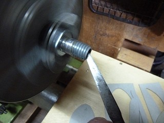
19.Chamfer the hole with a handmade scraper made from a file. |
20.Chamfer the other side in the same way. |
|
 |
 |
|
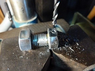
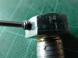
21.M4 pilot hole 3.3mm for rotation prevention on the bolt head. |
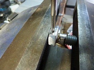
22.M4 tap. |
|
 |
 |
|
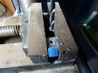
23.Similarly, make a 3.3mm pilot hole on the nut side. |
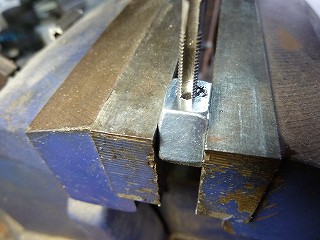
24.M4 tap. |
|
 |
 |
|
25.Screw in the M4 x 5L set bolt. |
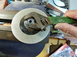
26.Fix the M12 bolt head in a vice, insert the diamond wheel and bushing sandwiched between flat washers, and tighten with an M12 nut. |
|
 |
 |
|
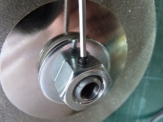
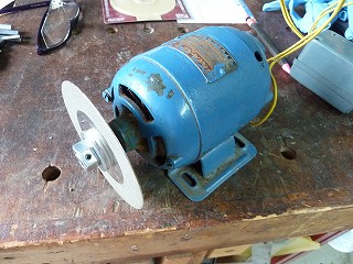
27.Insert the assembled diamond wheel set into the baby motor shaft and secure it with the M4 set bolt to prevent rotation on the bolt side, then screw in the M4 set bolt to prevent loosening on the nut side. |
28.I tried turning the baby motor, and there was no vibration, so the test run went well. However, there seems to be some strange noise coming from the bearings. |
|
 |
 |
|
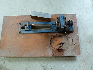
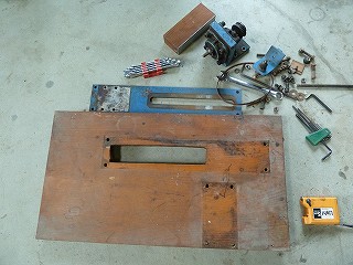
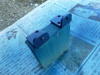
29.This is the remains of a wood lathe made in 1995 for making fishing floats. The baby motor was also installed here. |
30.I wanted to make use of the old parts, so I removed all the parts and decided to make good use of just the base board. |
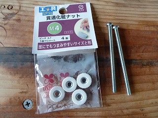
|
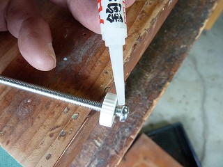
 |
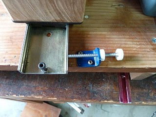
 |
|
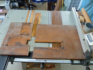
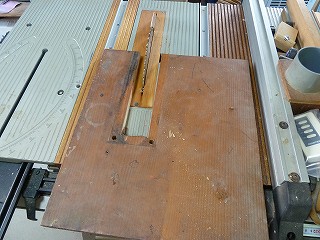
31.It's too big as it is, so cut it to a width of 430mm. |
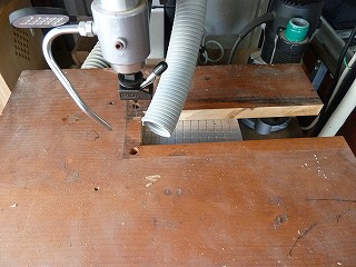
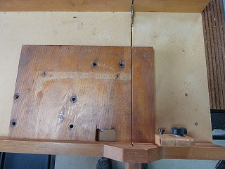
32.The grooves were straightened out. 29 years ago, I didn't have power tools, so I cut it with a hand saw, which resulted in some uneven straight lines. |
|
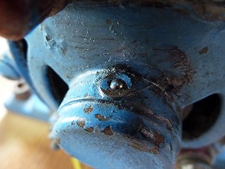
 |
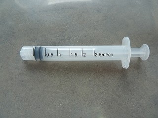
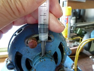
 |
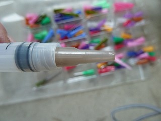
|
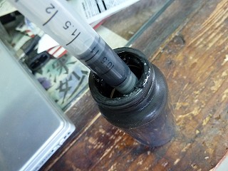
33.The short side of the groove was straightened using a scroll saw. |
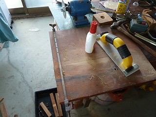
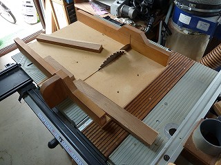
34.Cut out the parts to fill the grooves from the remaining base plate. |
|
 |
 |
|
35.Glue the grooved board with wood glue. |
36.I decided to make the leg plate attached to the back of the base board using leftover square lumber. |
|
 |
 |
|
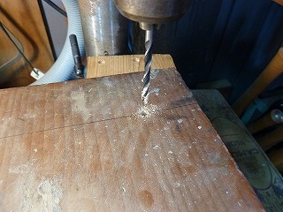
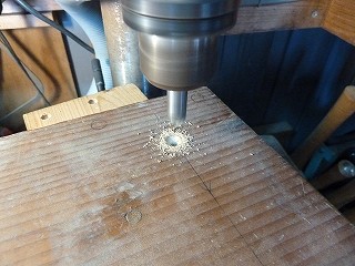
37.Dorilling for attaching the legs are 3.3mm. |
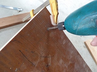
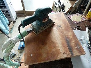
38.Counter sink. |
|
 |
 |
|
39.The legs are attached to the table using 3.3 x 38mm course threads. |
40.Seal the previous motor mounting holes with dowel plugs and sand them down. |
|
 |
 |
|
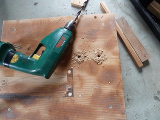
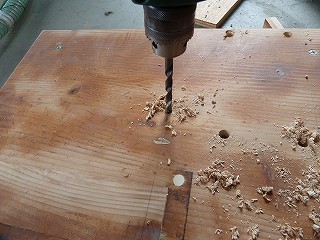
41.Drill four 8mm holes for mounting the motor base. |
42.This is a 6.5mm pilot hole for the M8 bolt that attaches the slide pack. |
|
 |
 |
|
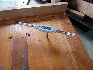
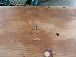
43.M8 tap. |
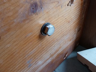
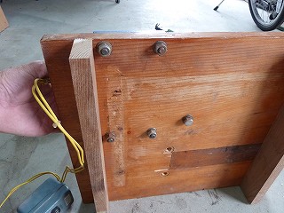
44.Screw in the M8 x 35L bolt from the back of the base. |
|
 |
 |
|
45.The M8 bolt protruding from the table serves as a pivot for mounting the slide pack. |
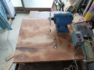
46.Attach the motor base with M8 x 40L bolts and nuts. |
|
 |
 |
|
47.After installing the switch box, it started to look like that. |
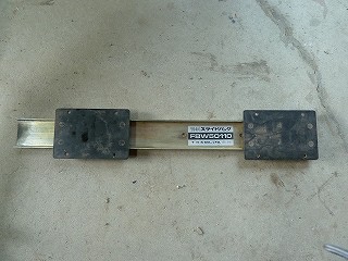
48.I decided to cut up this slide pack and use it as the part that slides the chip saw. |
|
 |
 |
|
49.It's THK's FBW50110. I think it's a leftover part from when I made a router lace jig for a woodworking lathe. |
50.Cut the rail part of the slide pack to a length of 230 mm. |
|
 |
 |
|
51.Drilled 8mm holes for mounting. |
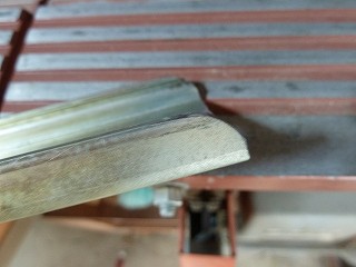
52.The pivot is tightened with a wing nut, so the end of the rail next to it is rounded to prevent injury from the edge. |
|
 |
 |
|
53.It's now safe to use. |
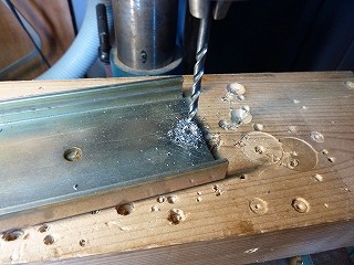
54.M5 pilot hole 4.2mm for the slide part retaining bolt. |
|
 |
 |
|
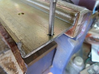
55.M5 tap. |
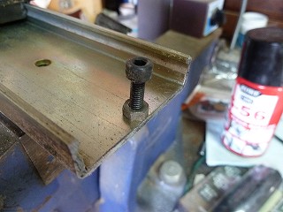
56.Install the M5 x 15L cap screw. Tighten it with a W nut to prevent loosening. |
|
 |
 |
|
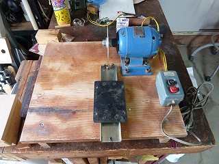
57.I tried attaching a slide pack to the base board. It feels good. |
58.From here, it's time to make an attachment to place the chip saw on the slide pack. |
|
 |
 |
|
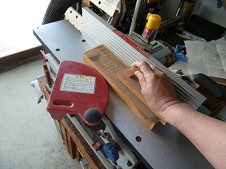
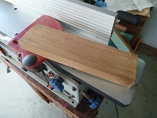
59.I had a piece of timber (probably ash) that was exactly 85mm wide, so I used a planer to flatten one side of it. |
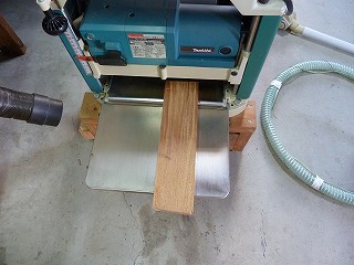
60.The thickness is reduced to 33mm using an automatic planer. |
|
 |
 |
|
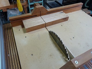
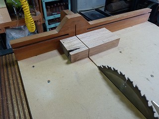
61.Cut it to a length of 125mm. This will be the attachment that will be attached to the slide pack. |
62.Cut another piece to a length of 125mm. |
|
 |
 |
|
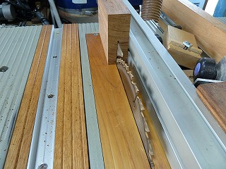
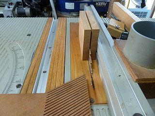
63.I was going to cut it to a thickness of 14mm, but I had a feeling it would be dangerous to cut it in one go, so I first made a cut 45mm deep. |
64.Then flip it over and cut it. |
|
 |
 |
|
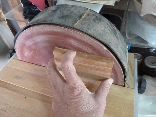
65.The cut surface had some slight bumps, so I sanded it with a homemade disc sander. |
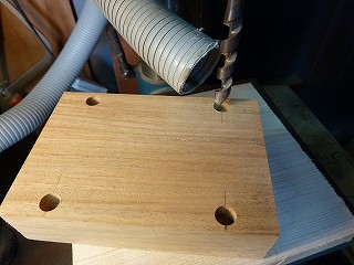
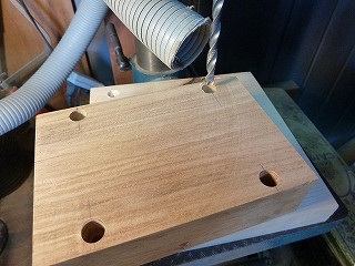
66.9mm counterbore, 11mm deep. |
|
 |
 |
|
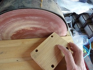
67.Drilling 5mm through hole. |
68.Round chamfered corners. |
|
 |
 |
|
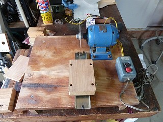
69.I tried installing it on a slide pack. |
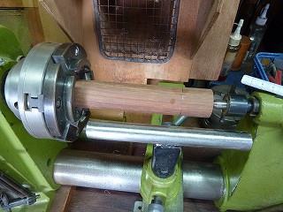
70.I had a round bar of rosewood available, so I decided to modify it to make the shaft for the chip saw. |
|
 |
 |
|
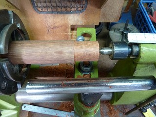
71.Turning to a diameter of 25.4mm. |
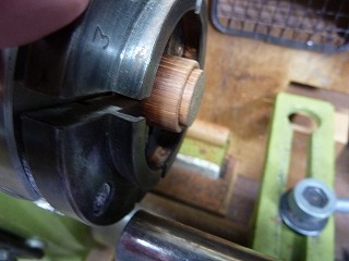
72.Cut to a length of 26 mm and turning the end face to 20 mm. |
|
 |
 |
|
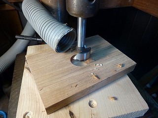
73.Drill 1 inch through hole in center of top attachment. |
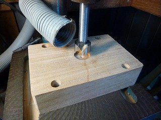
74.Make a 20mm counterbore for the lower attachment to attach the shaft. Depth 3mm. |
|
 |
 |
|
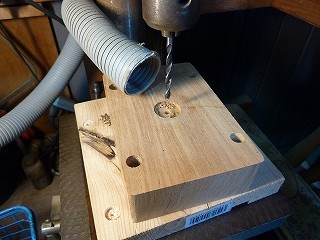
75.Drill a 4mm through hole in the centre of the counterbore. |
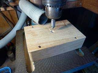
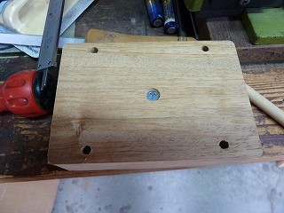
76.Make a triangular countersink on the back of the lower attachment. |
|
 |
 |
|
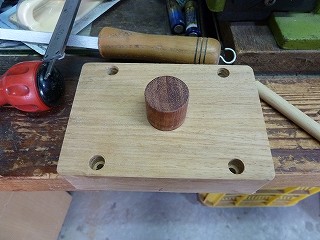
77.The rosewood shaft is secured in place with course threads. |
78.The production of the lower attachment is complete. |
|
 |
 |
|
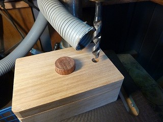
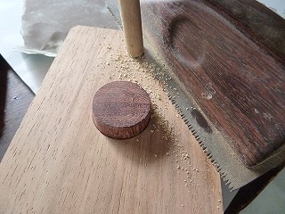
79.Drilling 10mm for locating pins. |
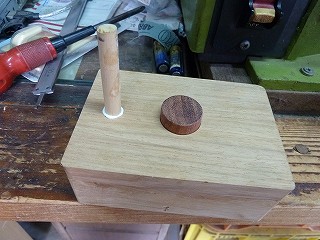
80.Glue a 10mm round bar. |
|
 |
 |
|
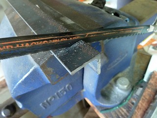
81.Cut off the protruding part with non-set teeth saw. |
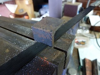
82.Assemble the attachment and sand so there are no steps. |
|
 |
 |
|
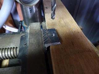
83.Now it's time to make the stopper for the rotation direction of the slide pack. Cut the 25 x 25 x 3 angle into 20 mm width. |
84.Cut one side of the angle to a length of 15 mm. |
|
 |
 |
|
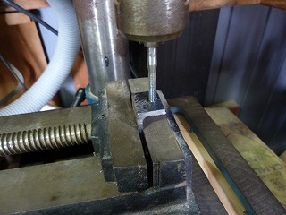
85.M4 pilot hole 3.3mm. |
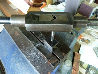
86.When machining M4 taps, the long screws wouldn't hit the target spot if they were slightly slanted, so I used a drill press to screw in the first few threads. |
|
 |
 |
|
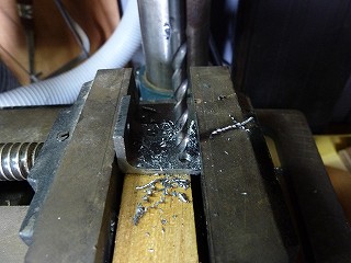
87.Remove from the drill press and tap. |
88.Drilling for the mounting screws. |
|
 |
 |
|
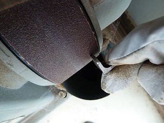
89.Round the corners with a belt sander. |
90.Paint it blue. |
|
 |
 |
|
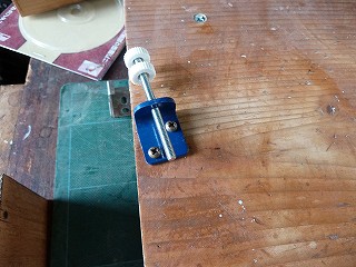
91.The stopper is a combination of an M4 through-hole decorative nut and an M4 x 60L round screw. |
92.Use instant glue to secure the decorative nuts in place so they don't come loose. |
|
 |
 |
|
93.Attach the stopper to the base plate with wood screws. |
94.This is the top left stopper. |
|
 |
 |
|
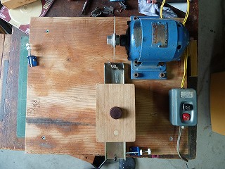
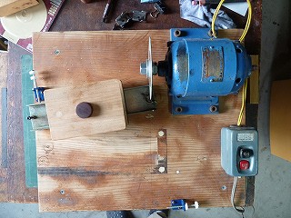
95.Position when grinding the end face of a chip saw. |
96.Position of the chip saw when grinding the outer circumference. |
|
 |
 |
|
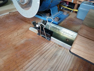
97.I tried using a double clip as a substitute for the slide pack's straight-line positioning stopper. |
98.When I tried to turn the baby motor, I noticed a nasty noise, so I decided to grease it up. |
|
 |
 |
|
99.I didn't have a grease pump, so I decided to inject it using a syringe I bought at a 1$ shop. |
100.Among the nozzles I had previously received from a dispensing nozzle manufacturer, I chose one that was slightly larger than the grease inlet and attached it to the syringe. |
|
 |
 |
|
101.Suck the molybdenum grease into the dispenser. |
102.When I placed it against the injection port and pushed it in, the grease went in perfectly. |
|
 |
||
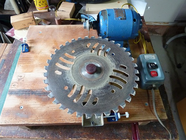
I tested sharpening with a worn-out tipped saw blade that I had been using for years. First, I sharpen the end surface. |
||
 |
||
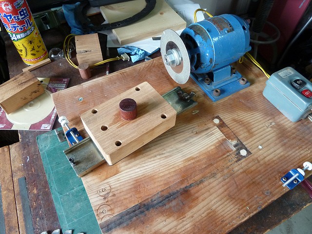
When sharpening the outer circumference, remove the top of the slide pack and rotate the slide pack counterclockwise until it hits the stopper. |
||
 |
||
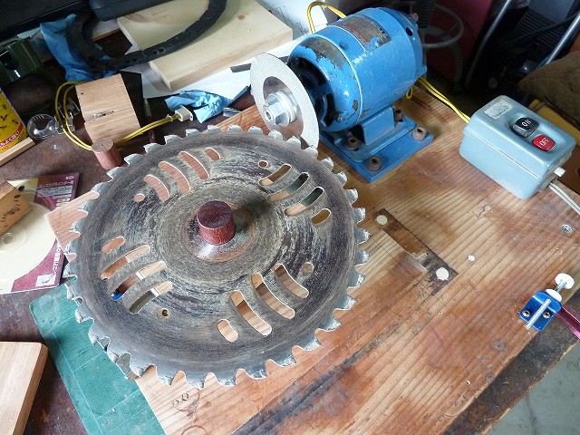
Flip the tipped saw upside down and install it and sharpen. |
||
When I used this, the stopper using a clip gradually shifted, so I remade it so that it would stay in place firmly. |
||
 |
 |
|
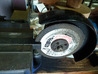
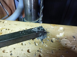
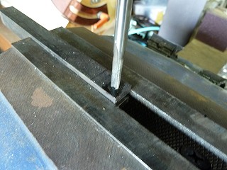
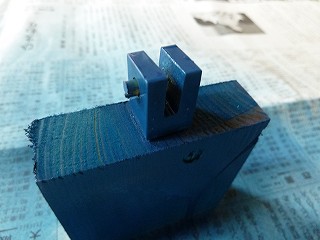
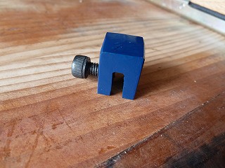
106.I had a 13mm square key, so I used a cutting grinder to cut a slit into the end of it. This is the groove to insert it into the slide pack. |
107.Drilling M5 pilot holes 4.2mm. |
|
 |
 |
|
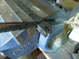
108.M5 tap. |
109.Cut to a length of 15 mm. |
|
 |
 |
|
110.Paint it blue. |
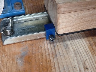
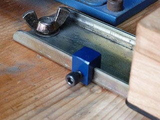
111.Attach the M5 x 10L hexagon socket bolt. |
|
 |
 |
|
112.Attaches to one side of the slide pack. |
113.I tried hitting the slide pack against the stopper several times, but there was no sign of it shifting. Good. |
|