Router(Trimmer) Lathe |
June 26/2005 Last year, I made copy-Jig for wood-lathe. However, the jig could not get high precision. I had the plan which the attachment is composed of to be able to use WT-300 as the trimmer lathe. [2009.12.21 I made synchronized gear unit for router lathe]
|
||
 |
 |
|
1.I had this plan because this THK slide pack is gotten from the my friend. I pictured a simple drawing. "Drawing" |
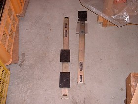
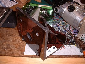
2.First, I began to make with trimmer stand.The material is PVC board. The thickness is 8mm, color is bronze. |
|
 |
 |
|
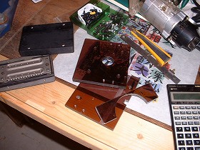
3.I cut them by the band saw. Moreover, I shear to the square by the trimmer. |
4.They are PVC part after the trim.Next time, I assemble these. |
|
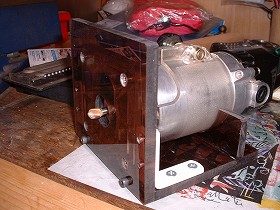
July 1/2005 Today, I assembles a trimmer and a stand. |
||
 |
 |
|
1.I assembles the part of use PVC in the screw and the glue. I used instant adhesive. |
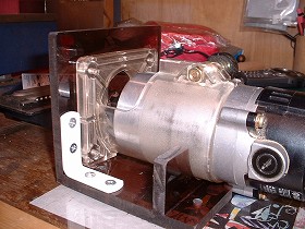
2.I attempts to do M6 in Hitachi at the mount. It is good. |
|
 |
 |
|
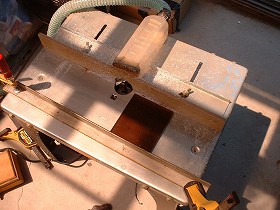
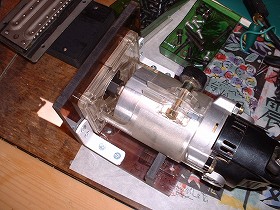
3.It is a rear figure. |
4.It sees from above. It is compact. |
|
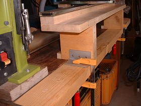
July 3/2005 Today, I made mainframe and guide parts. Frame is wood. |
||
 |
 |
|
1.I used the plywood of the rubber to have gotten from the friend, before. It is gluing after cutting. |
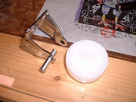
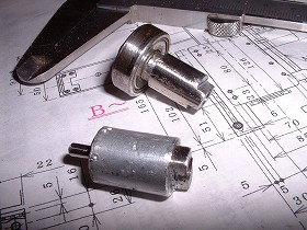
2.I makes a part for the guide. At first, I remodels a nylon caster. I removes and it break apart apart the part of the axis to three parts. |
|
 |
 |
|
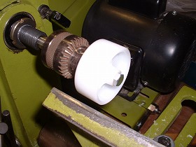
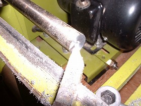
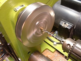
3.Generally, the wheel surface of the caster becomes convexity. I shears a wheel surface in the flat with the lathe. This wheel becomes the member which receives a radial load to the direction of Z (vertical). |
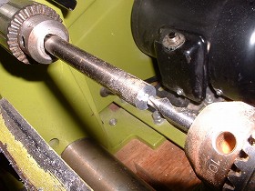
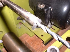
4.This rod is for the bearing which receives a radial load to the direction of cross side(Y). I drill a center correctly before making a tapped hole. |
|
 |
 |
|
5.I shears an end surface in the byte.It is possible to shear by wood-lathe. |
6.The M5 tapped hole is ø4.2m/m. |
|
 |
 |
|
7.Tapping |
8.I mounted a nylon caster and a bearing in the slide packing. |
|
 |
 |
|
9.The loading becomes such an image. The reason for using a nylon caster is noise prevention and cost-cut. |
10.I attempted to make the wheel of the zelkova tree experimentally. However, I didn't adopt because the precision was bad. |
|
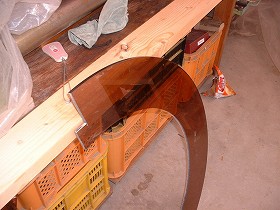
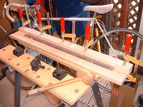
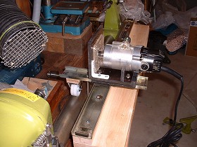
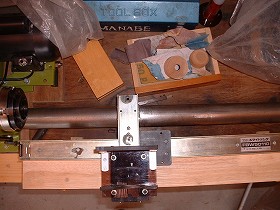
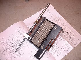
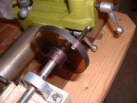
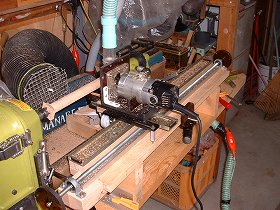
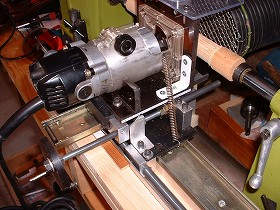
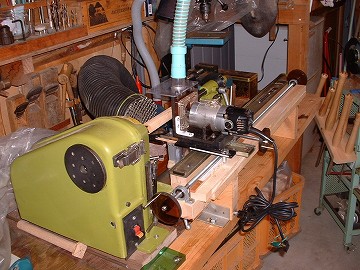
July 10/2005 I assembled frame, slide packing, a trimmer stand. The whole picture can be seen. |
||
 |
 |
|
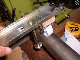
1.I attempted to move slide packing to back and forth either side. There is not vibration in it. It moves smoothly. |
2.The nylon caster and the bearing guide are supporting the circular bed of WT-300 tightly. |
|
 |
 |
|
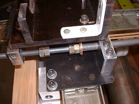
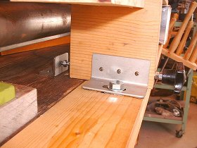
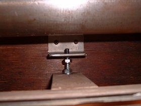
3.I installs a 40 mm angle in frame and it is fixing it on the Workbench with the F -type clamp.As for the Y axial direction, a position is decided with the stopper. |
4.The photograph from the upper part. |
|
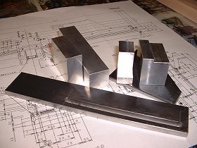
July 17/2005 I made the movement adjustment parts on the crossing side, brackets of the tracer, and brackets for the rubber band that pressed the slide packing against the template. |
||
 |
 |
|
1.They are parts cut from FB of the aluminum block and SS400 with the milling machine. |
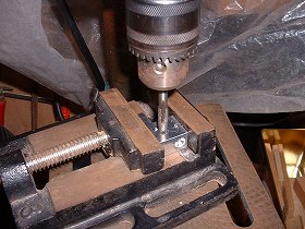
2.If drill press is used when the tap is set up, it becomes vertical. |
|
 |
 |
|
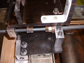
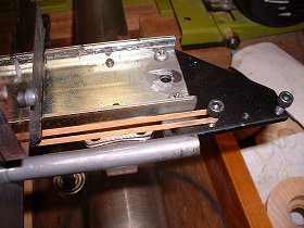
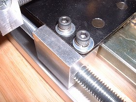
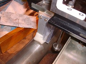
3.It is a position adjustment screw in the crossing side. |
4.It is the reverse which installed each part in the slide packing of the crossing side. |
|
 |
 |
|
5.The position adjustment screw part in the crossing side. |
6.The adjustment screw does the slide when the template is set and the slide packing on the crossing side moves along the template. |
|
 |
 |
|
7.It is a part of the rubber band that presses the slide packing against the template. It is good feeling that rubber was used because there was no suitable spring. |
8.It sees on. |
|
 |
 |
|
9.I made a handle. It is 8mmPVC. |
10.The knob inserts a pipe in the cap screw of M5. |
|
July 24/2005 I made the tracer of the template. |
||
 |
 |
|
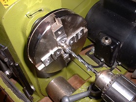
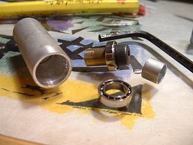
1.I cuts the aluminum pipe of caliber 10m/m, outside diameter 12m/m as in the drawing. and I shears the end of the with the lathe. |
2.I cuts 10m/m of SS400 circle sticks. It becomes the core of the aluminum pipe. |
|
 |
 |
|
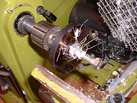
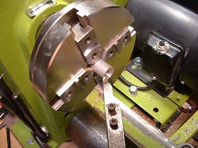
3.This strange chuck is Bantamchuck which removed Double-Tail-Jaw. |
4.I shear the shaft of the miniature bearing. The material is brass, ø 6m/m. |
|
 |
 |
|
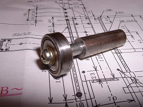
5.They are a parts. |
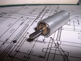
6.I assembled parts. The ø3m/m shaft traces out a template. It turns lightly. |
|
 |
 |
|
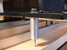
7.I installed in the router lathe. |
8.I made the tracer which used an a bearing for the straight line. I thinks that this is suitable for the curve and the taper cut. |
|
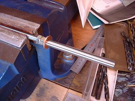
July 31/2005 I made lead screw. It is the screw to make a trimmer move to the direction of x. |
||
 |
 |
|
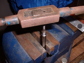
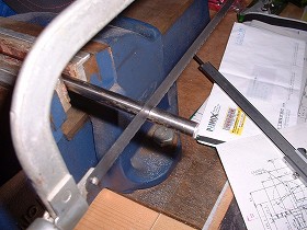
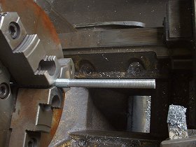
1.The screw is the length screw of M12~1000L. I bought at 365 yen in DIYshop. I shears its both edges in 10 mm of Ó with the lathe. The valley of the screw is stay but there is not a problem. |
2.It is the aluminum block part of the female screw. |
|
 |
 |
|
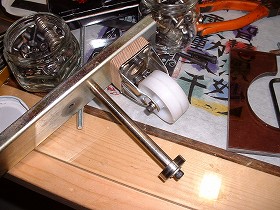
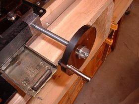
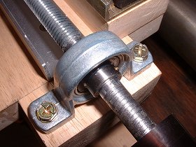
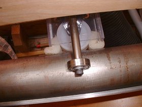
3.I fixes a pillow block on the frame. and adjusts height with the shim. |
4.I puts handle to the both edges of the screw.It moves lightly when I turn a handle. |
|
Aug. 7/2005 I wants to do test run early. However, it doesn't put dust port yet. The dust collector is an indispensable item. |
||
 |
 |
|
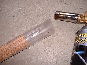
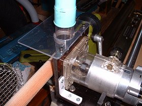
1.Because there was not a pipe which is suitable to the material of the hand durability, I glues together PVC with 0.5 mm thickness in the rounding and I makes it a circular cylinder. I heats it with the burner and I forms a tip at the eccentric nozzle. |
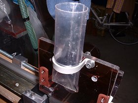
2.I makes U-band with aluminum board. and I fixes dust port on the desk stand base.
|
|
 |
 |
|
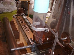
3.I connects a use dust port with the cleaner in the hose. |
4.The hose suspends with the rubber so as not to hang. |
|
 |
 |
|
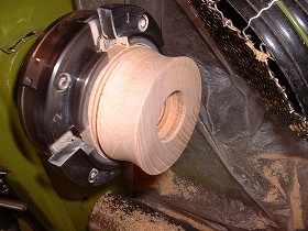
5.I begin a test run. Almost, I ascertains turning precision in the circle stick. The material is the square lumber of the chestnut. I turn it at the circle stick of ø25 mm. The bit uses U type. The noise is big. |
6.Dust port is working but dust flies into pieces above the expectation. The cover seems to have to be installed. |
|
 |
 |
|
7.The cut is favorable. However, the work rather becomes a taper. The frame seems to need a fine adjustment function. |
8.I attempted to replace U character bit with the straight bit. The finish of the surface becomes beautiful. |
|
Aug. 13/2005 I am the 1 week summer vacation from today. I reorganized some router lathe. |
||
 |
 |
|
1.The first remodeling is a mechanism that fine-tunes the stand position.
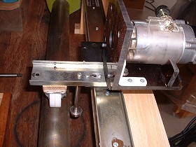
Work is made not to become a taper. The aluminum pipe of 6mm in the inside diameter is inserted in the leg, and both ends are fixed to it with w nut through the length screw of M6. To move by 25mm, the bolt hole of the angle for the frame fixation at the center was made a length hole. When it was possible to use it for the taper processing though it was within 1mm to move, it made it to the desire length hole. |
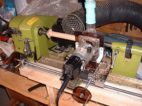
2.An angle is fixed on the Workbench. Therefore, the frame moves to before and behind when turning the black knob which can be seen in the right end with the photograph in front. |
|
 |
 |
|
3.I set a sponge to the place around the nylon caster. |
4.I put the cover to have made with clear PVC to the nylon caster. I thinks that there is not trouble which dust on the bed is due to in this. |
|
 |
 |
|
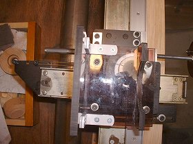
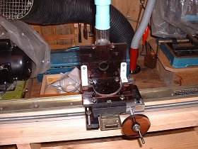
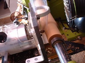
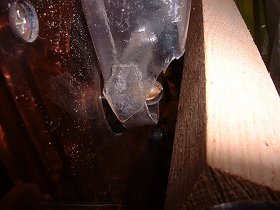
5.The point of the dust port enclosed surroundings of the bit. |
6.I mount a cover to the upper side of the stand in clear PVC.It was complete.@I will do use Spindle turning in this. |
|
 |
 |
|
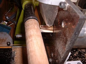
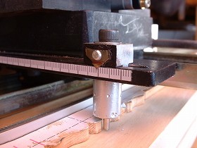
7.I cut the leg of the tracer shortly. |
8.I set a scale. |
|
 |
 |
|
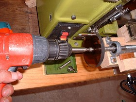
9.It pulls the body in the spring. It is a backlash measure. |
10.I uses an electric drill for the high-speed movement. |
|
 |
||